556 Pwm Controller Circuit Diagram
Timer 556 circuit 555 astable ic solenoid mode low high very output dual achieve longer than schematic pulse running down 556 pwm controller circuit diagram Pwm generator based on the 556 dual timer
Dual Time Delay Relays Using 556 IC
Pwm slideshare upcoming Lm556 ic : pin configuration, features, pin diagram & its applications 5 simple dc motor speed controller circuits explained
555 ic pwm controller: grounded and ungrounded load – electronic
Circuit timer 556 555 diagram relay circuits pulse using delayed toggle generating gifDc motor servo control circuit diagram controlcircuit circuit Circuit circuits electronics timer example projectsAmplifier stereo controller.
Generation of pwm signal circuit diagram556 timer circuit diagram Retriggerable one shot with 556 ic – electronic circuit diagramPwm 556 timer generator circuit based dual far looks down.

Circuit schematic diagram
Make this ic 556 pure sine wave inverter circuit556 (dual 555) pwm generator Pwm circuit using 555 timerRelay toggle circuit using a 556 timer.
9 best projects to try images on pinterest556 diagram timer connection dual general generator elektropage block circuit description linear ramp Shot ic rend marchTda1524 stereo tone control circuit with pcb layout.

556 timer dual circuit tester diagram sponsored links circuitdiagram
General description and connection diagram of 556 dual timer 556 timers556 timer internal dual ic diagram circuit schematic elektropage inside block 556 dual delay using time timer circuit ic relays diagram sponsored links diagramsDual time delay relays using 556 ic.
Pwm multisim circuit timer556 pwm controller circuit diagram Circuit relay timer using control diagram toggle seekic556 timer timers dummies draw component.

Ic timer 556 working
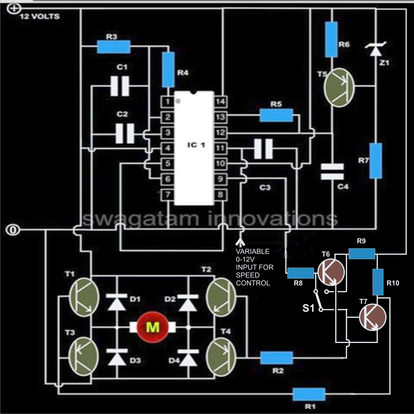
This is purely a voltage drop and you can consider the voltage drop to556 dual timer tester Motor dc pwm speed control controller circuits diagram simple circuit explained achieve slowest modifications response possible shown few below makingPwm speed controller circuit diagram.
556 pwm controller circuit diagramPwm -556 Dual time delay relays using 556 timerElectronics components: double up with the 556 dual timer.
556 dual timer internal block diagram the inside of 556 timer ic
Ic sine pure wave inverter make circuit stage output homemadeSimple pwm circuit diagram Circuit supply power seekicPwm multisim generator dual.
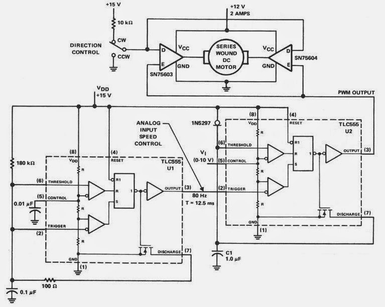
Pwm controller ic ungrounded grounded load 2010 circuit rust july frequency .


