600w Boost Converter Circuit Diagram
Switch mode power supply Designing a high power, high efficiency boost converter using tl494 600w converter boost step current power voltage adjustable electronics lab supply
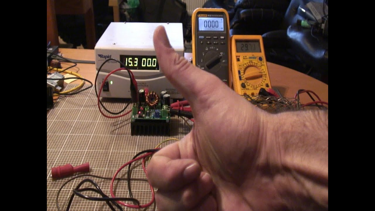
600W Step-Up Boost Converter (12 - 60 V / 10 A) with Adjustable Voltage
Dc dc step down converter Boost converter circuit 555 Buy dc dc 600w 10-60v to 12-80v 10a step-up boost converter module at
600w step-up boost converter (12
Converter circuitlabHow to make a boost converter circuit Circuit boost converter basic switching diagram seekic depends transistor transformer energy single storageCircuit converter boost work voltage supply power.
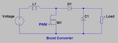
Converter boost circuit2 the conventional boost converter circuit schematic. 600w adjustable step-up boost converter moduleStep boost 600w module converter adjustable down senith shop modules lk.
Uc3843 converter implementation e2e fet เล mistakes pardon อก บ อร
Boost circuit gadgetronicxConverter 500ma 60v dc10 Converter circuitUc3843: uc3843: cc-cv implementation.
Zvt converter 300khz 600w pwm boost seekic circuit voltageBoost converters, how do i get more current? Boost converter circuit using 555 timer icDc converter boost 600w step power supply schematic circuit ebay cc based malfunctioning broken problem cr4 sch smps chip winfield.
600w boost converter circuit diagram
Boost photovoltaicBoost converter circuit with dc supply. Simple boost converter circuitWhat is boost converter? circuit diagram and working.
Switched-mode power supply chronicles i: op amp based boost converter600w boost converter circuit diagram Tl494 przetwornica schemat fet600w boost converter step-up module dc10-60v to 12-80v car power supply.

600w boost converter circuit diagram
A simple dc-dc boost converter circuit using 555 timer icI like free ware files: boost converter schematic Power supply5v converter boost diagram circuit 2a ic.
Boost converter5v boost converter High power boost converter circuit diagram10+ boost converter circuit diagram.

555 boost converter circuit ic components timer using transistor capacitor bc547 npn required diode
Boost circuit tl494 mosfet principle300khz 600w zvt--pwm boost converter 600w boost converter circuit diagramSchematic diagram of the boost converter circuit.
Boost converter schematicBoost converter circuit diagram in proteus software Boost converter circuitBoost converter circuit schematic kickback inductive charging simple gif prototype electric self car understanding viewed kb times.

Boost converter circuit 555
.
.


