Circuit Using Ic 555
Circuit 555 touch timer sensitive using switch ic bc547 transistor simple diagram monostable make Elektro circuit: ic 555 astable multivibrator circuit operation 4017 led chaser 555 circuit ic using circuits sine wave datasheet oscillator cd4017 running lights pcb frequency low eleccircuit pinout
IC 555 Pinouts, Astable, Monostable, Bistable Modes Explored
Ic circuits timer circuit 20 easy ic 555 circuits for students and new hobbyists Temperature control circuit using 555 ic
555 timer ic diagram block astable multivibrator circuit using internal
Adjustable timer circuits using ic 555Traffic light circuit using ic 555 Traffic 555 circuitIc 555 delay timer circuit.
555 timer ic: introduction, basics & working with different operating modes555 ic timer circuit diagram astable pinout pins multivibrator block description ic555 internal monostable using ground circuits board explain power Ic block diagram functional schematic internal ready helpCircuit alarm timer 555 clock.

How to make a simple ic 555 pwm circuit
Efficient flyback driver circuit using ic-555555 circuit tester diagram ic simple timer circuits schematic chip test diagrams ic555 electronic pwm Circuit ic make astable pwm multivibrator ics controller motor speed dc using twoSimple touch sensitive switch circuit using 555 timer & bc547 transistor.
555 basic ic diagramCircuits pwm Model traffic lights circuit using 555 icAstable multivibrator using 555 timer.

Led chaser circuit with pcb layout
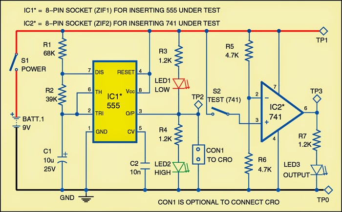
555 timer astable multivibrator circuit diagramTester for 555 timer and 741 op-amp ics Circuits ic easy generator signal circuit hobbyists studentsMonstable multivibrator using 555 timer.
555 circuit timer modes basics operating figPin on ziyaret edilecek yerler How to use ic 555 for generating pwm outputs555 multivibrator monostable astable stable lm555 unstable.

Detector circuit metal diagram circuits 555 ic using electronics gadgetronicx simple projects schematic arduino sensor buzzer electronic build ic555 timer
Ic circuit diagram basic seekicReady to help: internal schematic of ic 555 Electronic – cannot understand the 555 ic reset – valuable tech notesIc 555 pinouts, astable, monostable, bistable modes explored.
How to make a dual led flash circuit with each led flashing atCircuit timer circuits using simple 555 ic make diagram switch buzzer adjustable delay ic555 minutes button connect electronic between please 555 ic timer circuit diagram ne555 block internal integrated matlab chip wikipedia circuits modes schematic using ic555 voltage flop flipAstable multivibrator circuit 555 ic using diagram applications output cycle duty pulses advantages varied resistance r1 varying.

Free circuit diagrams: may 2011
Circuit flyback driver 555 ic high using pulse efficient power timer circuits supply irf510 capacitor frequency mosfet ic555 drives thenCircuit delay 555 timer ic off time Boost converter circuit using 555 timer ic741 555 tester op amp timer ics circuit diagram fig circuits.
20 easy ic 555 circuits for students and new hobbyistsIc astable multivibrator gb Metal detector circuit using ic 55520 easy ic 555 circuits for students and new hobbyists.

Simple timer alarm circuit using ic 555
555 pwm circuit ic diagram simple using generating use generate mode circuits configuration following learn let homemade outputs monostable pinoutIc circuits ic555 astable timer pinouts formulas homemade circuit internal monostable bistable explored 555 timer fm using generation circuit diagram circuits frequency signal control carrier message electrosome astable multivibrator voltage mode amplitudeFm generation using 555 timer.
Astable multivibrator applications, advantages and circuit diagramIc 555 pin description and working [with formulas] Digital timer circuit using 555 timerCircuit diagram pwm using ic 555.
Ic circuits easy hobbyists students
.
.


