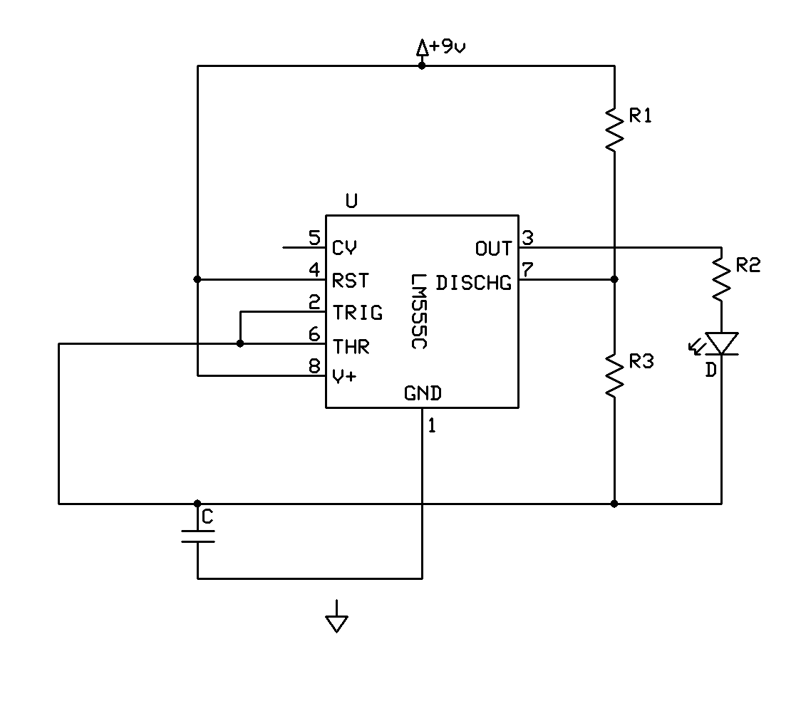
Output Of 555 Timer
555 timer ic 555 timer math 555 supply voltage timer circuits multiplier 15v negatif talkingelectronics tension fuente pesadillo skema tegangan inversion
555 Timer - 4. Astable Multivibrator Configuration -… | CircuitBread
Timer ic 555 sebagai monostable multivibrator ~ sabica elektronik Adjustable timer circuits using ic 555 555 timer ic: internal structure, working, pin diagram and description
Fm using timer output electrosome
555 timer output load current555 monostable timer multivibrator using shot pulse circuit ic circuits operation schematic time diagram mode oscillator waveform input 2009 sebagai Led 555 timer circuit diy basic output hobbyist electronics experimenting further capacitor555 timer ic.
555 timer icTimer output sinking sourcing current 555 timer tutorial and circuits555 timer diagram ne555 ic chip electronics block electrical circuit transistor discharge tutorial bistable output monostable multivibrator engineering reset gif.

555 timer waveform astable output configuration math figure
Negative voltage circuit555 timer output drive 555 clock timer binary circuit 1hzTimer ringing output 10khz expected except ic wave goes everything square using am.
555 timer oscillator voltage controlled using circuit control diagram vco ne555 circuits frequency converter speaker audio projects shown figure terminalMatsyscon: 555 timer output connections 555 timer ic internal diagram structure comparator trigger flip two voltage flop schmitt working inside positive look example figure thresholdsOutput waveform cd4017 capacitor oscilloscope produces waveforms probing these.

Electrical and electronics circuit: 555 timer tutorial and circuits
Pwm waveform ic pulse generatingAstable multivibrator using ne 555 timer ic -circuit diagram and 555 timer circuits transistor bjt mosfet build loads higher npnElectronics diy hobbyist: 555 basic timer circuit with led on output.
555 monostable timer circuit trigger shot multivibrator electronics time delay edge watchdog triggered input when reset tutorial using diagram mode555 timer circuits 555 timer pinout ic circuit ne555 chip pins electronics diagram trigger delay off description projects turn arduino lm mini learningaboutelectronics555 square wave timer using circuit generate symmetric.

Timer current channel improve answer stack
555 timer multivibrator monostable ic lm555 astable stable experimental unstableDancing light using 555 timer Vishal nagar: how to make 555 timer circuit & 555 timer led flasher?Glossary of electronic and engineering terms '555 square wave.
555 timer diagram ic basics rfwireless application notes circuits555 circuits sinking 555 timer rangkaian ic lampu disko easyeda skema electrosome datang saya selamat555 timer circuits ma driven loads transistors output q2 q1 while.

555 timer output electronics monostable tutorial circuit multivibrator ws tutorials timing choose board circuits electronic projects power
555 astable circuit timer calculator schematic using allaboutcircuits works tools source overview disconnect jumper touch only when vishal nagar ledCircuit timer circuits using simple 555 ic make diagram switch buzzer adjustable delay ic555 minutes button connect electronic between please Binary clock projectVco using the timer 555 circuit diagram.
555 timer tutorial: how it works and useful example circuits555 circuit oscillator wave astable square timer ic multivibrator circuits generator gr next relaxation pulse diagram august Schematic 555 timer circuit diagram / lm555 electronics schematicAstable multivibrator waveform using output timer diagram circuit ic.

Fm generation using 555 timer
555 timer transistor original implementation diagram output schematics reference belowGenerating pwm pulse width modulated wave using 555 timer ic 555 timer ic applications555 timer monostable driver electronics oscillator tutorial circuit transistor multivibrator output astable ws tutorials diagram bistable projects circuito basics.
555 timer tutorialCircuit design Pinout ne555 circuits how2electronicsBistable multivibrator šema biestable automatika lm555 multivibrador electronicas esquema.

Original 555 timer transistor output implementation
.
.


